How to Use the Kinematics App in 3DEXPERIENCE
Table of contents
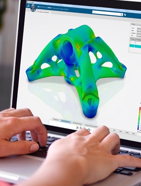
The Kinematics app within 3DEXPERIENCE allows you to develop your parts into functional assemblies by furthering the functionality of the engineering connections used within the Assembly app. This means you can either create a mechanism specifically for the purpose of checking the functionality of your design or you can modify a design you’ve previously created to run this tool and validate your design.
Types of Mechanisms
There are various types of mechanisms within the app to enable you to develop a comprehensive kinematic system including:
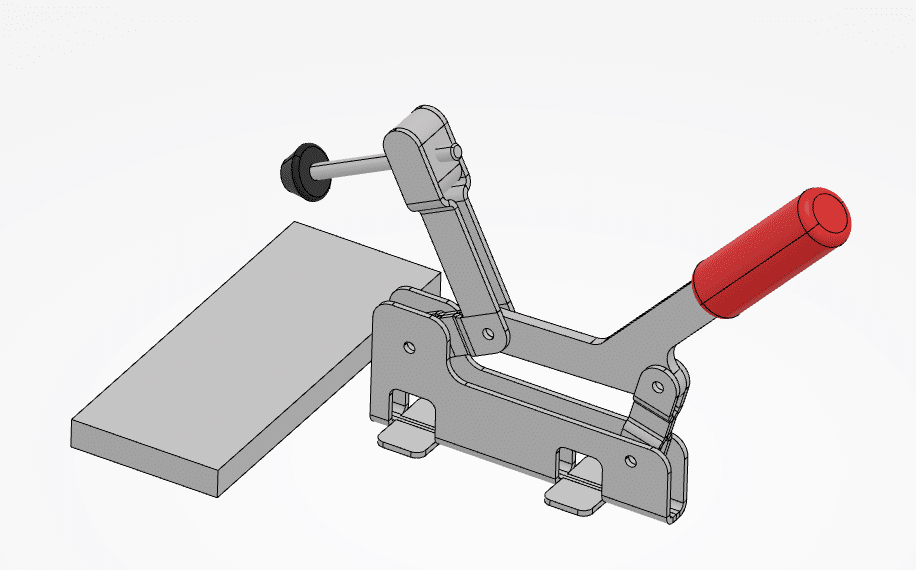
- Linear linkages such as those you would find on a Toggle clamp (shown below) to more complicated set ups such as automotive suspension.
- Rotary / linear linkages can provide reciprocating motions which are commonly used within special purpose machinery and are visibly demonstrated on the drive wheels of a steam train.
- Screw connections allow you to replicate the helical motion using both the linear translation in conjunction with the rotation of part. This can be found in a bench vice or on a lathe lead screw.
- Cable joints can be used to show a linear movement of one component transferred to the linear movement of another component on a different path. This is commonly seen for changing gears on a bicycle or where a lift is attached to a counterweight.
- Belt or chain drives can be replicated by pairing rotating pulleys or sprockets and applying a drive ratio (i.e. 2:1) to simulate the motion of these systems. This can help you to verify that the input you have specified will have the desired outcome and can be especially useful when combining with other mechanisms. This is commonly seen on the front of an internal combustion engine where the crankshaft is used to power the ancillary systems.
- Gearing mechanisms, including rack and pinion systems, work similarly to those defined above in the belts example though these have a direct connection between each other as opposed to the motion being conveyed by a belt or chain. These types of mechanisms are commonly found in drivetrain gear boxes as well as steering systems.
- Sliding and rolling surfaces can be used to replicate motions where two components are touching but not mechanically linked. An example of this is with cam designs where you have a cam shaft and a cam follower. This is also an example of where rotary and linear motions combine to give the desired result.
Spur Gear
Worm Drive
Rack and Pinion
Belt & Pulleys
Cam Follower
Linkages
The examples provided are that of common applications but the possibilities to develop your ideas and use this powerful tool are much greater.
Manual Control
When using the Kinematics workbench, you can either:
- Apply control to a singular assembly, or,
- Control multiple sub-assembly mechanisms within a top-level general assembly using a single control point (Macro Mechanism) for each of the mechanisms contained within the top-level general assembly.
This gives a lot of flexibility to replicate the desired motions. And to understand the required sequence and duration of movements which achieve the result.
Doing this can help you to understand the limitations of the current design. This logically leads to improvements which enable greater flexibility and functionality. These systems can either be controlled using the slider bar in the dialogue box (shown below) or by dragging the components in 3D space.
In addition to the manual movement of the sliders or components, you can also add virtual motors to the joints to show the required motions. These can be controlled with parameters including speed, distance, and oscillation.
Laws and Design Tables
An alternative means of controlling the models is by using excitation laws and design tables. This allows you to accurately control a sequence of motions. It allows for concurrent control of multiple motions if required. In the video below you can see an example of this being used where the spindle on the toggle lever clamp is extended before the handle of the clamp is operated.
Assembly ‘Dress up’ Functionality
The Kinematics app includes a feature called ‘Dress up’ which allows you to link the definitions from a wire frame driven mechanism to the actual components so that the functional verification of the design is more representative of the end application.
Interference Checking
One of the most useful tools within the kinematics tools are the interference checking capabilities. This shows up where any collisions may happen within the defined parameters of your assembly. Or, instead of showing the collisions, the assembly can stop on contact of these components. This will display the limitations of achievable motion within the design.
This is a great tool for finding limitations within your design and ensuring that these issues are designed out. You can also check pathways of components and distances between components as part of this verification process. This is demonstrated in the video below.
This video shows three scenarios:
- Clamp wrongly adjusted showing the clamping head interfering into the workpiece. This highlights the area where the interference happens.
- Model parameters are changed to make the clamp movement stop when the clamping head touches the workpiece. This highlights how the clamp is wrongly adjusted and the lever mechanism is unable to go over centre.
- Spindle screw is adjusted to all the clamping head to contact the workpiece after the clamp had gone over centre.
In Our Experience…
These tools can be used to help develop designs including tooling, jigs and fixtures, supporting and simulating the suspension geometry for automotive and motorsport. We even provide training to help customers take these tasks on in-house.
These simple principles can be applied to much more complex designs. What’s more is that they help to reduce development costs by ensuring potential issues are noticed early on. And solutions can be developed before components are manufactured and real life tests are undertaken.